Door positioning is fundamental to cabinet design: it controls aesthetics, clearances, and function. For cabinet engineers and specifiers, the single most important geometric control inside a cabinet hinge is the crank — the intentional bend or offset in the hinge arm that sets where the door sits relative to the cabinet face.
In this article, Mingrun, a professional cabinet hinge manufacturer, explains the crank’s role in plain engineering terms, shows how crank geometry interacts with cup position and mounting-plate height, and offers practical guidance for choosing and verifying hinge geometry for overlay, inset, and partial-overlay installations.
What the Crank Actually Is (and Why It Matters)
The crank is the lateral offset in a hinge arm that displaces the hinge pivot axis away from the door surface. In a cabinet hinge, that offset determines whether the door overlaps the cabinet stile, sits flush inside the opening (inset), or partially covers the cabinet face (partial overlay). Mechanically, the crank changes the moment arm and the door’s lateral position, so a small change in crank depth can produce a significant change in visual overlay and clearance behavior.
Key reasons the crank matters:
- It defines door setback and overlay without changing the cabinet carcass geometry.
- It interacts with the mounting plate height to permit fine adjustment.
- It affects internal stress distribution and the hinge’s fatigue life.
How Crank Geometry Shifts the Pivot Axis
Consider the hinge as three linked geometric elements:
- Cup position (C) — the distance from the door edge to the edge of the cup drilling (often called “Tab” or “K-distance”).
- Hinge Constant (K) — the inherent horizontal offset determined by the Crank of the hinge arm (Straight, Half-crank, or Full-crank).
- Mounting-plate height (P) — the vertical/axial offset provided by the plate; notably, increasing plate height decreases the door’s lateral overlay.
These elements combine to set the door edge position relative to the cabinet face. The accurate engineering formula is:
Overlay (O) = K + C – P
This is the standard formula used by manufacturers (such as Blum or Hettich) for selection and early-stage layout, as it accounts for how the plate thickness pushes the hinge arm away from the side panel, thereby reducing overlay.
Typical values (industry ranges — illustrative):
- Drilling distance, C: ~3–6 mm
- Hinge Constant, K: ~13 mm (Straight), ~4 mm (Half-crank), or ~ -5 mm (Full-crank/Inset)
- Mounting plate height, P: 0–4 mm (standard plates)
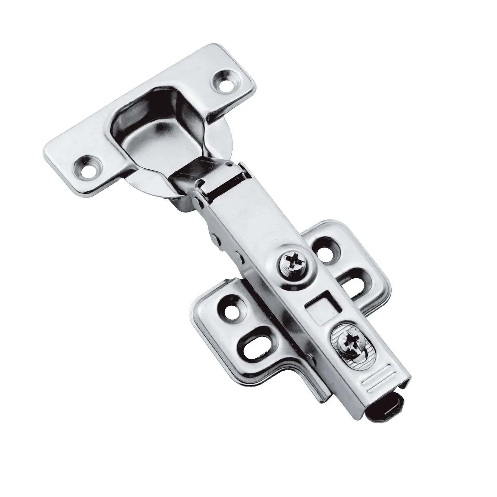
Crank Types and Door-position Outcomes
Zero crank (straight arm)
- Behavior: The pivot axis is positioned to allow maximum lateral extension of the door relative to the cabinet side panel.
- Use cases: Full-overlay applications where the door must completely cover the cabinet face or side panel.
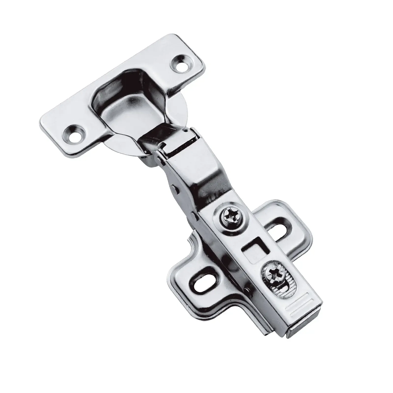
Half crank (typical for half overlay hinge)
- Behavior: Moderate offset that pulls the door partially inward, reducing the coverage on the cabinet stile.
- Use cases: Half-overlay (dual-fit) layouts, allowing two doors to share a common partition while maintaining a gap between them.
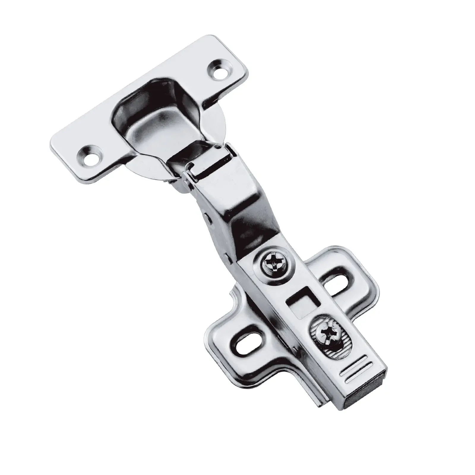
Full crank (deep offset)
- Behavior: Maximizes the inward displacement of the hinge arm, shifting the door entirely inside the cabinet opening.
- Use cases: Inset (flush-fit) doors where the door sits flush with the cabinet face rather than covering it.
Small geometry changes between these types result in noticeable changes to overlap and clearance. Selecting the correct crank type early avoids rework, as plate adjustments cannot compensate for an incorrect crank selection
How Mounting-plate Height and Cup Position Fine-tune the Result
Crank geometry provides the bulk of the lateral offset, while mounting-plate height and cup drilling are the fine controls:
- Mounting-plate height (P): This is the quickest field method to adjust the overlay without swapping hinge arms. Increasing the plate height reduces the overlay by pushing the hinge arm away from the side panel. Most standard plates offer a height range of 0mm to 4mm, providing a critical final adjustment for door alignment.
- Cup drilling distance (C): The distance from the door edge to the edge of the cup must be set according to the desired overlay and door thickness. Increasing this distance (C) directly increases the overlay, as it moves the pivot center further onto the cabinet stile.
Important rule: You cannot reliably “compensate out” a grossly wrong crank selection with plate height alone. Plate height has limited travel; if the crank is significantly off, the door may still collide or sit incorrectly.
Structural Implications of Crank Depth
The crank not only positions the door but also alters load paths:
- Bending moments concentrate at crank bends; designers add ribs or thicker cross-sections at these zones to reduce fatigue.
- Lever length created by deeper cranks increases torque on pivot pins and fastenings, requiring stronger pins or reinforced cups.
- Motion smoothness can be affected: complex cranks may require different internal cam profiles to prevent dead spots.
Selecting a cabinet hinge with properly reinforced crank geometry is vital for heavy doors or frequent-use applications.
Practical Selection and Verification Checklist
Use this checklist when selecting or specifying cabinet hinge crank geometry:
- Define overlay target: Specify the required overlay (mm) for your cabinet design based on side panel thickness.
- Request hinge geometry data: Ask the supplier for the Hinge Constant (K), Drilling Distance (C), and available Plate Heights (P).
- Run the overlay calculation: Use the industry-standard formula O = K + C – P to compute the theoretical overlay. (Note: Ensure $P$ is subtracted, as thicker plates reduce overlay).
- Verify cup compatibility: Ensure the cup depth is compatible with your door thickness to avoid “blow-out” on thin materials.
- Check plate adjustability: Confirm the mounting plate offers sufficient +/- adjustment (typically ±2 mm) to fine-tune alignment on-site.
- Inspect structural reinforcement: Look for structural ribs or gussets around crank bends, especially for heavy-duty or stainless steel applications.
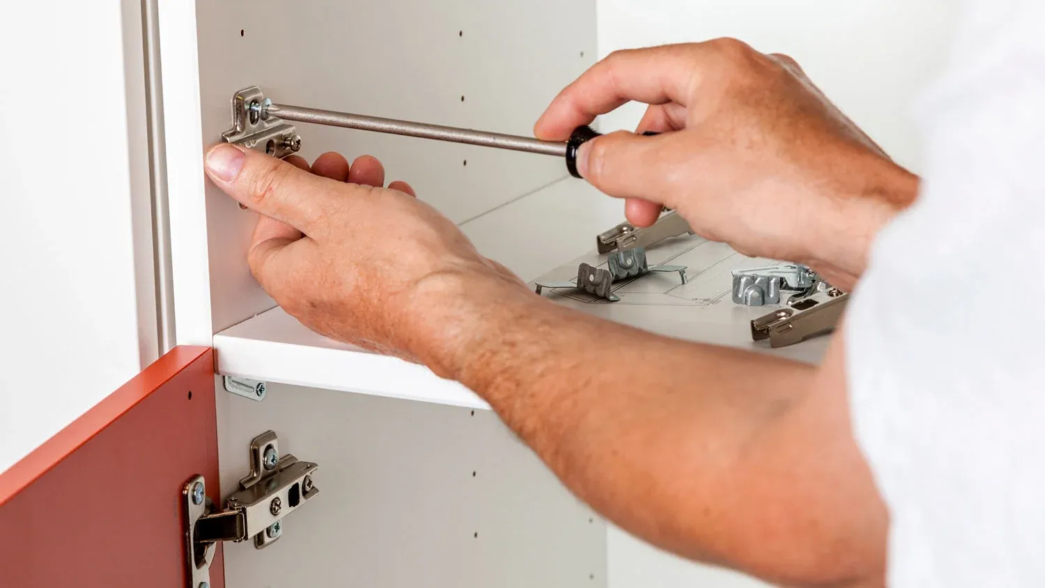
- Test assemble a sample: Physically trial-fit a door on a mock-up to validate clearance, pivot trajectory, and smooth motion.
Conclusion
For designers and buyers working with a cabinet hinge, the crank is the key geometric variable that determines whether a door will overlay, inset, or partially overlay the cabinet face. Understanding the interplay of cup position, crank offset, and mounting-plate height — and validating those dimensions with sample assembly — prevents misalignment, collisions, and premature wear. Treat crank geometry as an engineering decision, not a cosmetic detail, and you will save time, cost, and fitment headaches in production and installation.
About Mingrun

Mingrun is a professional cabinet hinge manufacturer focused on precision hardware for furniture applications. We supply wholesale cabinet hinges and deliver custom cabinet hinge solutions tailored to specific door structures, load requirements, and installation standards.
As a factory-direct hinge supplier, our production operates under internationally recognized safety and quality frameworks, supported by controlled processes and consistent output. From material selection to final inspection, every hinge is engineered for stability, durability, and reliable performance—making Mingrun a dependable manufacturing partner for global furniture brands and projects.